ECE5725 Final Project
RoboGPT- an AI Powered Robot
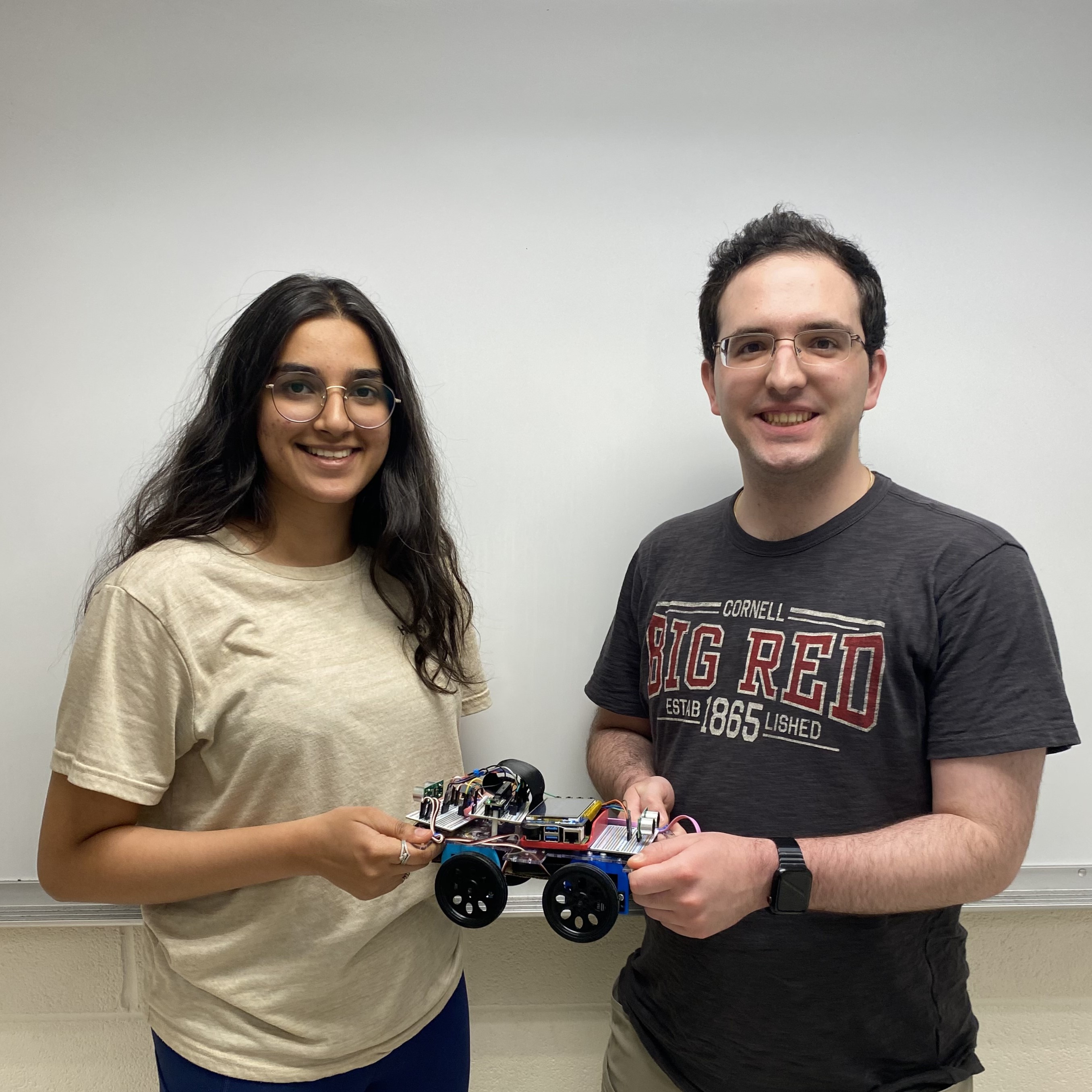
A Project by Raphael Fortuna and Rabail Makhdoom.
Demonstration Video
Introduction
This project is a small AI-Powered mobile robot platform centered around using cloud AI services and Raspberry Pi 4. We are using four continuous rotation servos mounted on a laser cut acrylic sheet. For our sensors, we are using an accelerometer and gyroscope, two ultrasonic sensors on the front and back of the rover to avoid running into obstacles, a microphone to collect audio input, and a bluetooth speaker to play sounds back from the robot. The robot software uses Azure Speech Services for speech-to-text to transcribe user requests and text-to-speech for the robot to talk to the user. It also uses the OpenAI ChatGPT API with a custom prompt that processes user requests and returns a response that includes what the robot should say or do. ChatGPT’s role here was to take a high level command, like “draw a square with sides of 1 meter” and create lower level movement commands that the robot should run, allowing the robot to have a large degree of functionality and responsiveness to most commands. The Raspberry Pi collects data locally, sends data to the cloud AI services, uses the sensor input to avoid hitting obstacles while moving, and processes the ChatGPT response to move the robot and talk to the user.
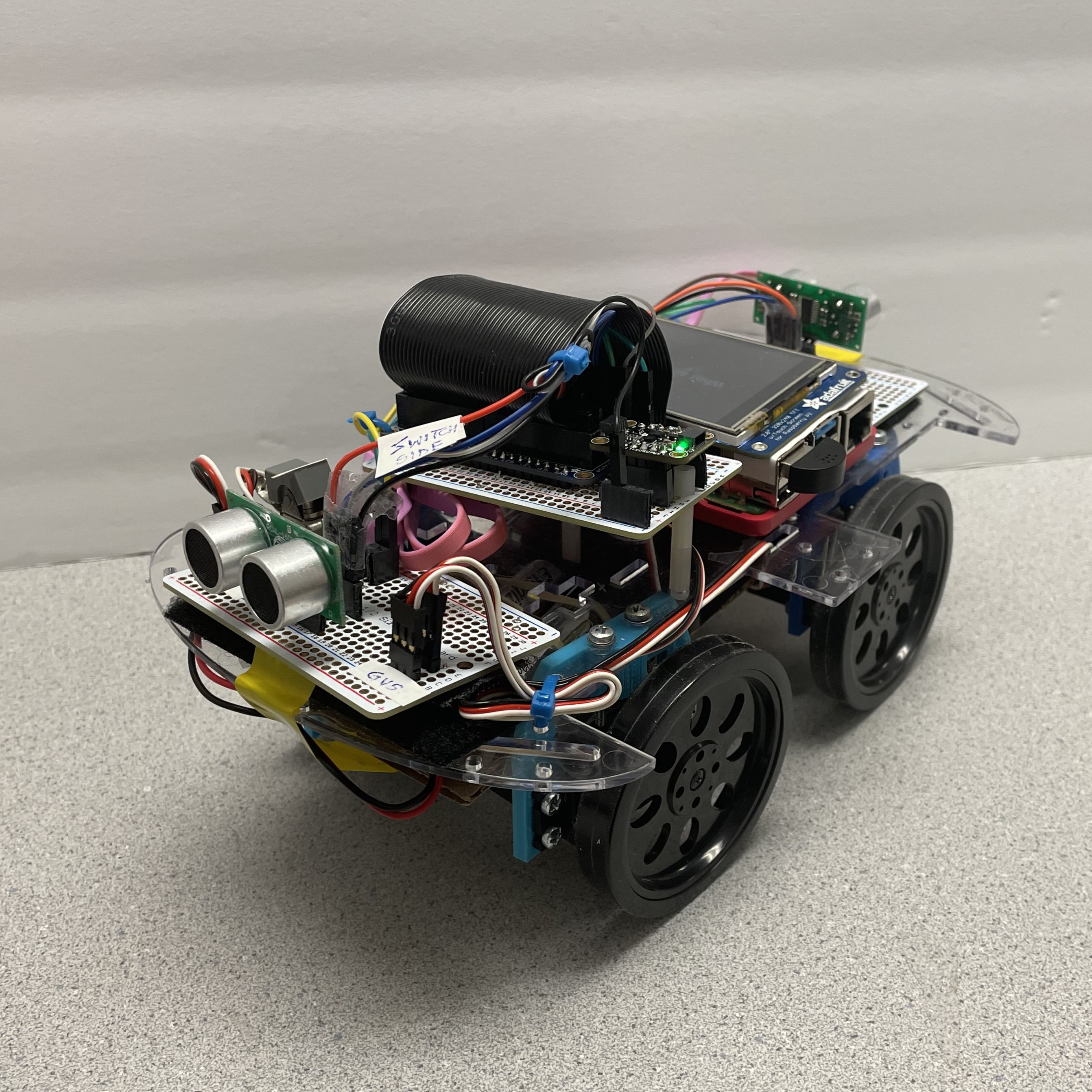 Side View of Robot
Project Objective:
- Create an AI-Powered Robot
- Be able to communicate with the robot and give it commands using speech-to-text and text-to-speech conversion
- Sense the distance of any obstructions in front and behind the Robot to prevent it from running into things.
- Display actions of the robot on the piTFT screen
Our project objective was to create a mobile AI-Powered Robot that can understand verbal commands, move based on those commands, and respond back to the user. The robot takes in user input using speech recognition, sends the converted text to ChatGPT, processes the returned response to get movement commands, and then uses text-to-speech to respond to the user. The robot has two ultrasonic sensors and an accelerometer and gyroscope that it uses for its safety controller and sends sensor data to ChatGPT. There is a piTFT screen on the robot to let the user know when the robot is ready to receive commands and what it is currently doing.
Design
Software Design
The design process began with seeing if using all the cloud services on the Pi was feasible. We created small demos of the speech-to-text, text-to-speech, and OpenAI ChatGPT API. All these services had their own API documentation that had to be reviewed to build the different mini-demos. Links to the API documentation are included in the references section below. After creating each demo, a full-scale demo was integrated together with each service to test a simple AI assistant that you could talk with. After integrating the cloud services into a demo, another ChatGPT prompt and instance, trainerGPT, was created to act like a user and talk to the ChatGPT instance with the prompt the robot would be using, robotGPT. This was helpful in quickly testing the prompt and finding strange corner cases - like how commands were sent. trainerGPT provided a feedback summary at the end to see how robotGPT’s prompt could be improved. trainerGPT also used another ChatGPT prompt and instance, dataGPT, to create synthetic data to send to robotGPT to further test it and see how it understood incoming data.
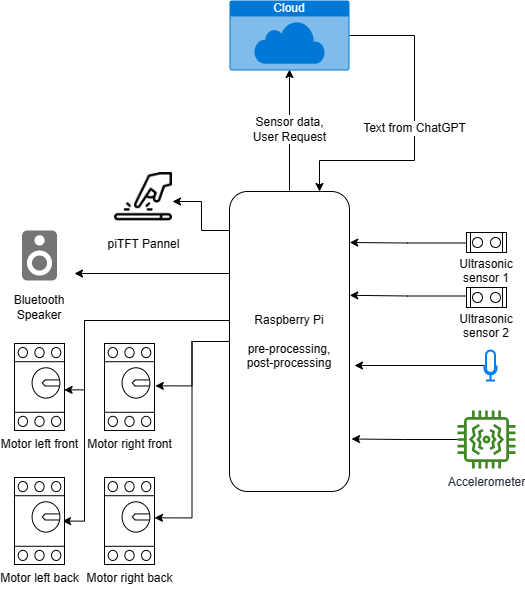 Data Flow Diagram
Alongside the trainerGPT testing, command parsing was added to robotGPT’s output by parsing the text and removing strings that were wrapped like so: ### command(value) ###. This made it easy to parse the commands and the text that was not a command was spoken using speech-to-text. Using trainerGPT to test each change code or prompt change that was made alongside manual testing helped speed up testing and made it easier to find edge cases.
The next step in the software development was integrating the services on the Raspberry Pi. The Azure Speech Service Python library required a 64-bit Raspberry Pi OS, but our OS was 32-bit and so we had to modify both the speech-to-text and text-to-speech modules. The speech was sent to Azure using the Python SpeechRecognition module and an onboard USB microphone plugged into the Raspberry Pi. For text-to-speech, we used the Azure Speech Services REST API to get the audio file of the speech.
For playing the audio from the text-to-speech, we had initially used PyGame to play back .mp3 audio files, but it was inconsistent with playing the files, so it was replaced with the Python VLC module that used bindings with Python to play the audio files. The audio was played using a bluetooth speaker to save space and reduce weight on the robot.
Once the demo with all cloud services integrated could run on Raspberry Pi, the code for the sensors was integrated into the Pi. We looked at the ultrasonic sensor and accelerometer and gyroscope documentation to interface with them. Both modules had CircuitPython support, a Adafruit library for interfacing different sensors with Python libraries made for them by Adafruit. The code for both sensors was developed using the libraries provided by Adafruit and installed during the hardware and software integration below. The motors also got their own code and used Hardware PWM instead of software PWM or CircuitPython to reduce any delays in the PWM signal that could cause the motors to shake or drift when stopped.
The next software component developed was what tied all sensors and cloud services together under one class. This became manager.py and managed getting and refreshing sensor data, collecting text from speech, using the robotGPT module to communicate with ChatGPT, and controlling the motors. Below is the state machine that describes how manager.py processed data and controlled the robot. To ensure the loop ran as quickly as possible while the robot was moving, each robot movement was packaged into the actionUnit class that was used to keep track of how long the action needed to be run for and if it has run for this amount of time. This was because all the robot movements - turning left, turning right, forward, and backwards - were all based on timing as we were able to calibrate and tune the motors with enough accuracy to use timings.
Returning to the state machine, it first checked if the robot had completed its current action, if it had one, and then stopped the robot if it had completed the action or had no action and checked if there were any more actions in the action queue. This queue was filled with the commands that were processed from the ChatGPT response. If there were more actions, they were run, otherwise robotGPT received the current sensor data and that the robot had stopped moving. robotGPT’s response was then spoken back to the user. New user commands would then be collected and responded to by robotGPT and added to the action queue to be run. While the robot was moving, the ultrasonic sensors would check if the robot was too close to an object and if it was, the robot would stop and prompt the user to resume the robot’s movement.
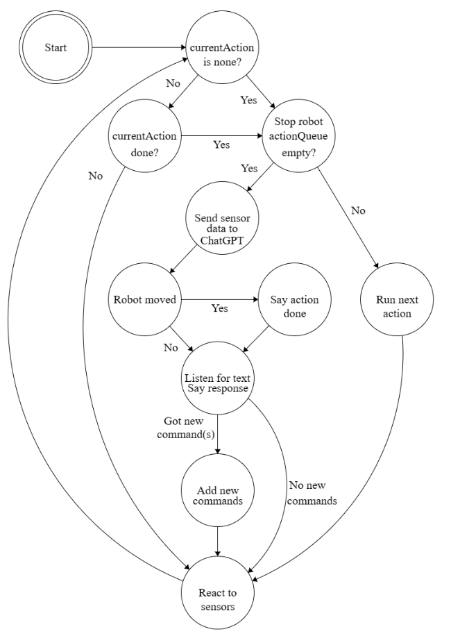 State Machine for Implementation
The final software component was the piTFT display to let the user resume the robot movement, switch from speech based commands to text based commands, and let the user know what the robot was doing and if it was ready to listen to new commands. We used Pygame to display text on the piTFT but ran into issues running the piTFT alongside the manager.py code. The piTFT code, display.py, required a “sudo” when run from a ssh terminal for it to be displayed on the piTFT. This worked fine on its own, but running manager.py with sudo required installing the packages it used though sudo and broke the functionality of several python modules. So, we created a fifo file that was sent text to display by manager.py and was continuously read by display.py. If the fifo file contents differed from the previously read data, the piTFT display would be updated to show this new data. This made it really easy for any module or code to send text to the piTFT for testing and let the user know what the robot was doing. This was especially important when collecting user speech and making sure the user knew when the robot was listening to them to avoid speaking before the robot was ready and having to repeat their commands. If the robot activated its emergency stop (EStop) due to being too close to an obstacle, the class in manager.py would stop the robot, save what command was being run and how much time it had left, then send resume through the fifo to be displayed on the piTFT. This added “Resume -->” to the piTFT screen and pointed to the physical button that had to be pressed to resume the robot’s movement.
These buttons were managed by the class in manager.py and were used to resume the robot’s movement and toggle the user input to either be speech or text. We used physical buttons on the piTFT instead of the touchscreen because the touchscreen became less responsive as piTFT got hotter from usage.
With all of this together, we went through extensive testing further described in the testing section to make the user experience better and reduce robot errors.
Hardware Design
Our circuit schematic of the robot is shown in the figure below. The Raspberry Pi acts as the central controller for the robot and is powered by an external power bank. The continuous servo motors were powered by a 6V battery pack and the two ultrasonic sensors and accelerometer and gyroscope were powered by the Raspberry Pi. We added a switch to the servo circuit to make it easier to test the robot without it driving away. Two ultrasonic sensors are used to measure the distance in front and behind the robot to ensure it does not run into any objects. Each sensor takes in a trigger input and outputs an echo signal for distance sensing. The accelerometer and gyroscope are also used to keep track of the speed and orientation of the robot. All sensors connect directly to the Pi GPIO pins and each sensor gets 3.3V and GND from the Pi. These signals are broken out on a protoboard on the robot and header pins are used to allow for easy wiring and any replacement of damaged sensors or wires.
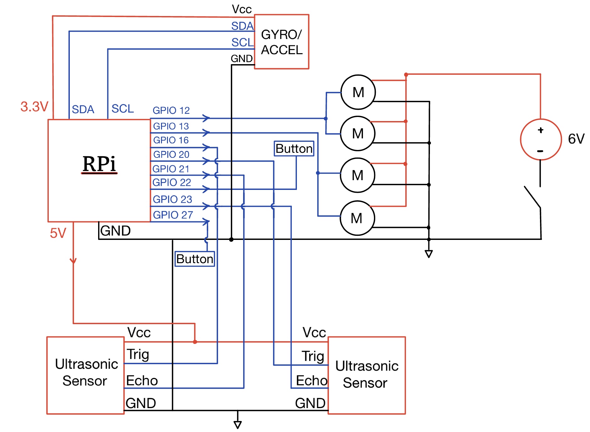 Hardware Diagram of Robot
The power signal is connected to a 6V supply that comes from an external battery pack and the GND pin is shared with the Raspberry Pi G ND. The signal pin for each motor connects to PWM signals taken from the Pi GPIO pins. Since hardware PWM was used to control the servo motors, we only had GPIO 12 and 13 at our disposal and thus both of the left motors were controlled by GPIO 13 and both right motors were connected to GPIO 12.
We started with seeing where we wanted each sensor to be placed on the robot and how we wanted to organize them on solder boards. We chose to use solder boards to reduce connection issues from loose wiring and added headers to connect the sensors so that they could be easily swapped if they broke. We used an acrylic robot body and four 3D printed motor braces from class to hold all our components. We then soldered and tested all the sensors and tested them with the code for each respective sensor. To use the sensors, we had to install CircuitPython from Adafruit. CircuitPython is a programming language based on Python for working with microcontroller boards. Adafruit has libraries that provide drivers that interact with CircuitPython and Python to make it easy to control sensors from Python. The installation process is in our Github repository Read Me linked at the end of this website.
After installing CircuitPython and the libraries for the sensors, we tested all the hardware as described below in the testing section.
Drawings and Photos
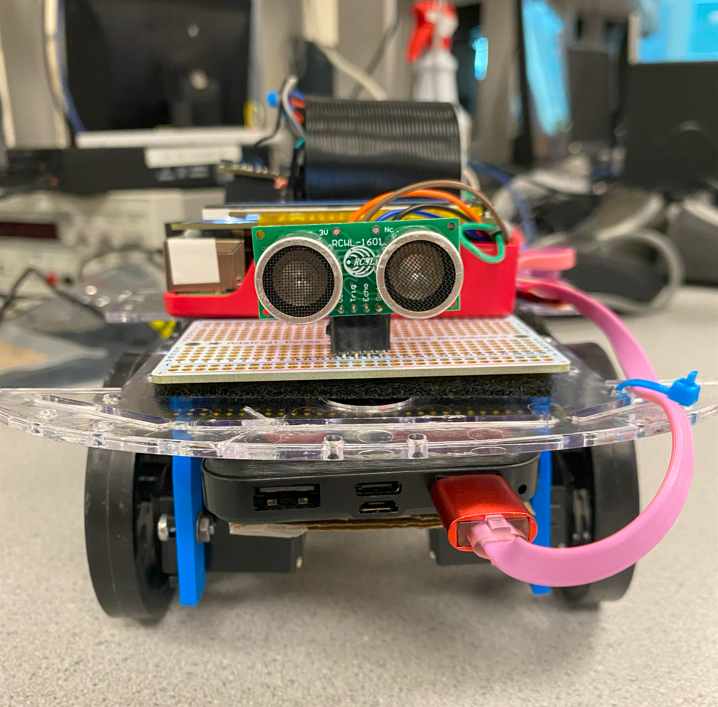 Front of Robot
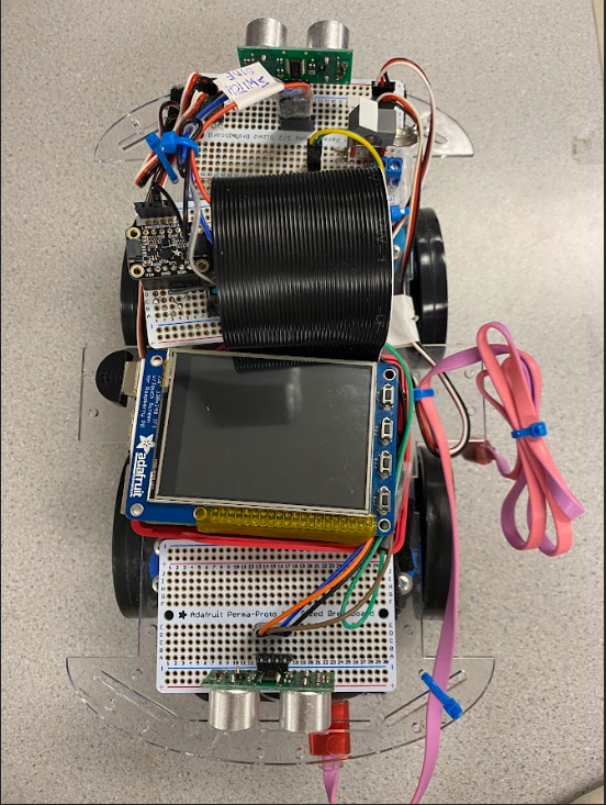 Top view of Robot
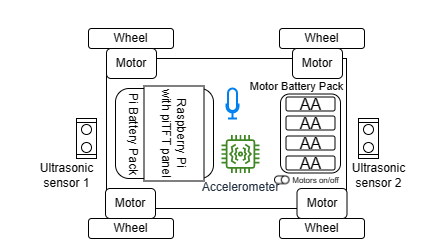 Robot Sensor Diagram
Testing
Sensor Testing
We tested the sensors incrementally. First, the hardware was tested individually and test scripts were made to ensure all components were working and returning the expected outputs. To make sure that the motors were running in the correct direction and that their output movements matched their input controls, we measured the PWM outputs with an oscilloscope. We used the equation, (pulse width)/(pulse width + 20) * 1e6, to send the correct duty cycle at 50 Hz based on the Parallax Continuous Servo datasheet, linked in the references section. It was initially scaled at 1e5, but this caused the PWM signal to be jittery and the motors were unresponsive until we fixed this issue. The ultrasonic and gyroscope sensor data outputs were also tested separately in two different scripts and print statements were added to ensure that the data output matched the expected results.
The ultrasonic sensors intermediately returned very noisy values, so we took the median of five different sensor measurements, all within around 10 milliseconds, and this heavily reduced our noise and improved our accuracy. This also reduced the false positive EStops that would stop the robot if it got a small noisy value. We also confirmed that the ultrasonic sensors did not interfere with each other even though they both measured data at the same time.
The accelerometer and gyroscope connected by I2C did not require any modifications during testing and worked well with the other sensors.
Software Testing
As mentioned in the software design section above, we used another ChatGPT prompt and instance to test the robot’s ChatGPT prompt and get feedback on how it did with each change we made, which made it much easier to test and iterate on our prompts - especially with our prompt containing over 200 words of robot controls sent to the model.
Robot System Testing
Once the hardware was tested we moved on to testing the robot system. We spoke into the microphone and gave the robot different commands and added text to let the user know when they should talk to make it easier to use. We also added error handling to the cloud services and made sure it would gracefully retry the operation if needed instead of crashing and creating a poor user experience. For example, by saying “move forward 1 meter” into the microphone, we made sure that the robot moved the required distance in the right direction and then outputted that it was done into the bluetooth speaker. Similar other tests were performed to find corner cases and make sure the robot was working as expected.
We had a small public demo and used the feedback to improve how we let the user know what the robot was doing. We used the piTFT to display when the robot was listening to speech and when it was performing the required task.
Results and Conclusions
We were successfully able to talk to the robot, have it act on our commands, and talk back to us to let us know what it was doing. We were able to have it move in a square, octagon, pentagon, and in other different movements - all from asking the robot to move in the specific shape or movement and having ChatGPT break that high level command down into little chunks that the robot could complete.
We initially planned to use the accelerometer and gyroscope for feedback control when moving but found that the robot was very accurate when it was moving and turning so we were able to move the robot based on time and sent the sensor data to ChatGPT to let it know how fast the robot was moving. The ultrasonic sensors kept the robot from hitting objects and made it very reliable and reactive. The robot was able to avoid collisions even when confronted with multiple nearby objects.
Future Work
Future work could involve exploring a couple options. We could use the gyroscope and accelerometer data to detect various terrains under the robot. We could also potentially connect a camera to the robot that would allow the robot to move in a straight line by careful adjustments of the motor PWM signals based on the camera input. This camera could also be used to implement object detection and add even more complexity to the AI program.
Work Distribution
Team
Raphael
raf269@cornell.edu
Focused on software design of the project, incorporating AI and sensor outputs together.

Rabail
rm857@cornell.edu
Focused on mechanical assembly and hardware design of the robot.
Parts List
- Raspberry Pi 4
- Breakout cable and pinout
- piTFT
- 4 robot wheels
- 4 3D printed braces
- Laser-cut base
- 3 solder boards
- Zip Ties
- Header Pins
- Jumper Wires
Provided in Lab:
- 2x Ultrasonic Distance Sensors - $7.90
- 1x Accelerometer and Gyroscope - $20.0
- 12V Battery Pack - $8.00
- 4x AA battery - $5.00
- Power Bank - $25.00
- 4 Continuous Motor Servos - $40.00
- OpenAI API costs - $2.00
- Microphone - $5.00
Extra Parts:
Total: $112.90
References
GPIO
Speech-to-text
-
Azure Speech SDK samples and
quickstarts
-
Recognizing
speech-to-text with Azure
-
Using the Python SpeechRecognition Library
Text-to-speech
-
Text-to-speech
with Azure
-
Text-to-speech
with Azure Speech REST API
-
Text-to-speech
example with Azure Speech REST API
OpenAI API
-
OpenAI chat completion
-
Prompting the chat completion
-
Prompting the chat completion
-
OpenAI chat completion
quickstart
CircuitPython
-
Starting with
CircuitPython
-
Raspberry Pi 4B CircuitPython installation
instructions
-
I2C address,
enabling I2C, and pins
-
I2C Protocol overview
-
I2C list of addresses
Sensors and Servos
-
Accelerometer shop page
-
Accelerometer Python library from
Adafruit
-
Ultrasonic shop page
-
Ultrasonic sensors with
CircuitPython
-
Ultrasonic Python library from Adafruit
-
Student
project with ultrasonic example
-
Continuous Servo
Datasheet